Ripples
I enrolled in this class at NYU, called Creative Computing, driven by a deep-rooted fascination with merging code and physical elements—like LEDs—to create art. This venture is essentially an exploration of the synergy between visually captivating objects and the underlying code that animates them. It prompts a return to the fundamental question I posed at the outset: what is the purpose behind crafting such pieces?
Motivated by this inquiry, I aimed to develop pieces that not only engage the user but also delight the senses. From the beginning, my ambition was to encapsulate the dynamic interaction elicited by a person's touch upon water's surface. This vision laid the groundwork for the design concept I envisioned.

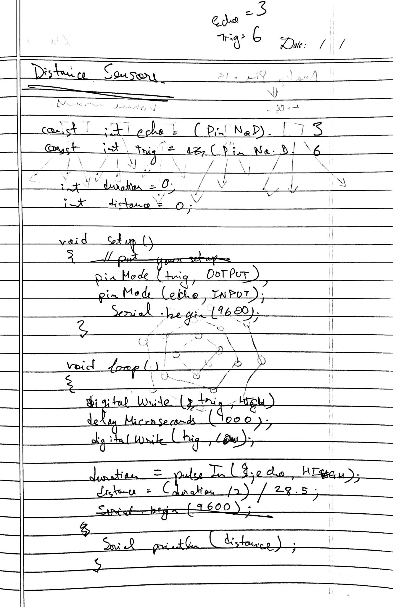
Following my professor's advice, I narrowed my focus to a single ripple, employing LEDs controlled by an Arduino Nano 33 IOT.
I discovered that by connecting my LEDs to the analog pins, I could control their brightness. After designing a graph for my code's impact on the LED circuit, I realized the need to reduce the scale of my project by 70% in terms of LED usage, leading to the final design.
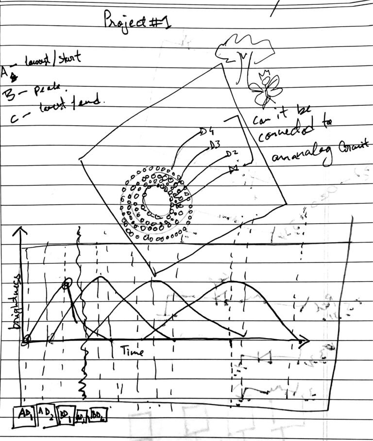
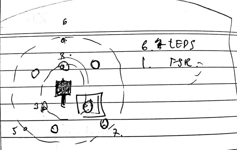
When the force sensor would be activated in the middle of the circuit of LEDs, the LEDs would light up in the way I wanted them to.
After testing the light patterns I came up with the first prototype for the project.
As I envisioned scaling the project, I explored broader possibilities. Our class's progression into P5.js, alongside lessons on integrating Arduino code with P5 sketches via serial connections, opened new avenues. Intrigued by the idea of depicting the water's surface on a screen while maintaining physical interaction externally, I decided to construct a trackpad using nine touch sensors available from the ITP shop. This is the approach I planned to take.

Seeking to expand the project, I turned to P5.js, learned in class, to connect Arduino code with P5 sketches through serial connections. Inspired to simulate water's surface on screen while keeping the interaction physical, I envisioned creating a trackpad using nine touch sensors from the ITP shop. This was my strategy moving forward.
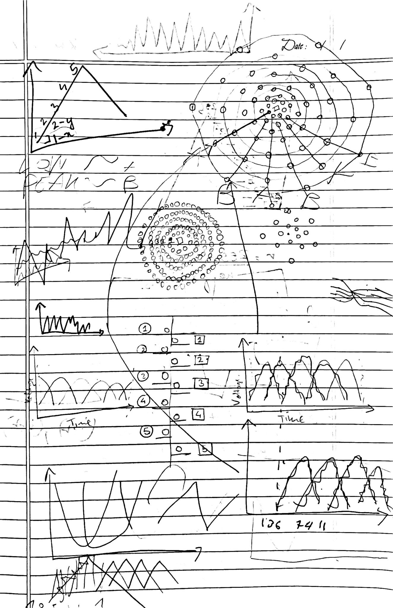
I decided to arrange my nine sensors into a small square of a cardboard box and then give them co-ordinates. When a particular sensor would be activated, a ripple pattern would be formed at that co-ordinate on my computer screen, using the co-ordinates on the p5 canvas. Every sensor was connected to an Analog input in the Arduino circuit.

I arranged the sensors on the cardboard, mapping their layout before integrating them with the Arduino positioned beneath. After identifying and removing the non-functional sensors, I finalized the setup. This is a photo of the interactive component.


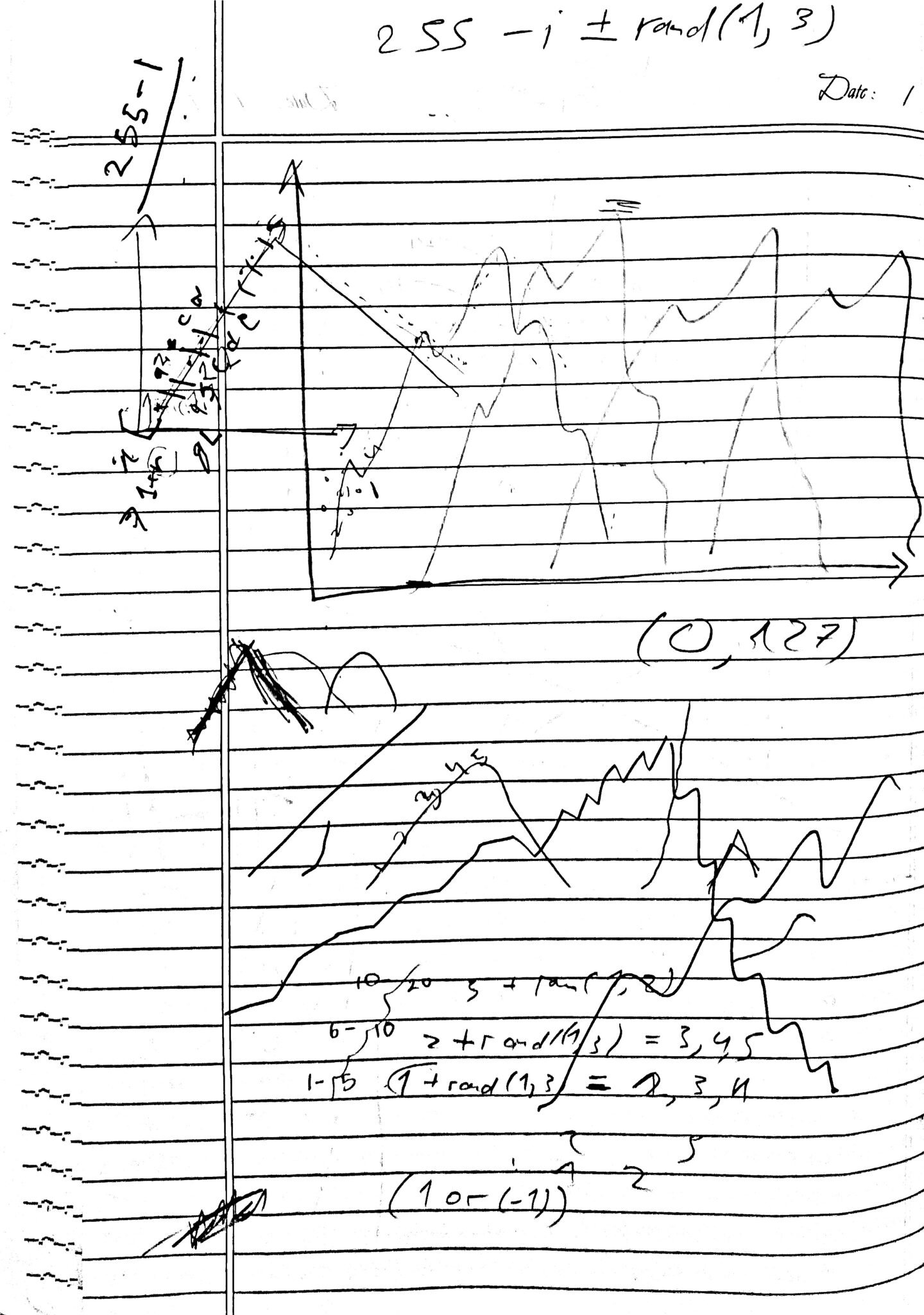
I then developed a P5 sketch designed to generate a ripple pattern at specific screen coordinates. To perfect the ripple effect, I experimented within a separate Arduino sketch, leading to the creation of the final version. Here is the sketch that emerged from this process.
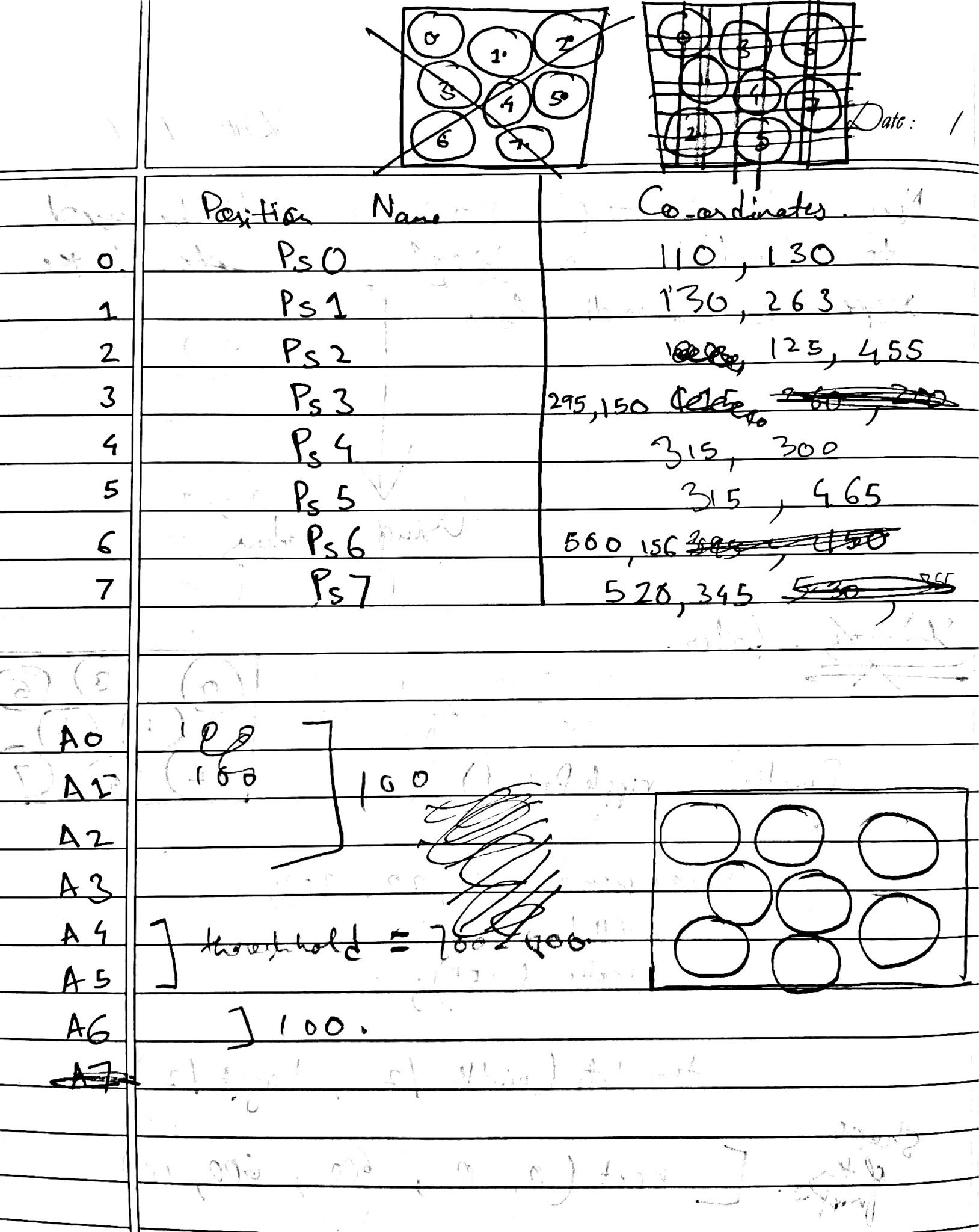
Each time a sensor was triggered, its corresponding code was encapsulated in a method, which was then invoked for the specific sensor's coordinates. Below is the chart developed through a process of trial and error.
For my final project, I aimed to scale up significantly, moving beyond P5.js on my professor's advice to expand upon my initial concept with a comprehensive circuit. I sought to innovate, opting for different physical components and interactions.
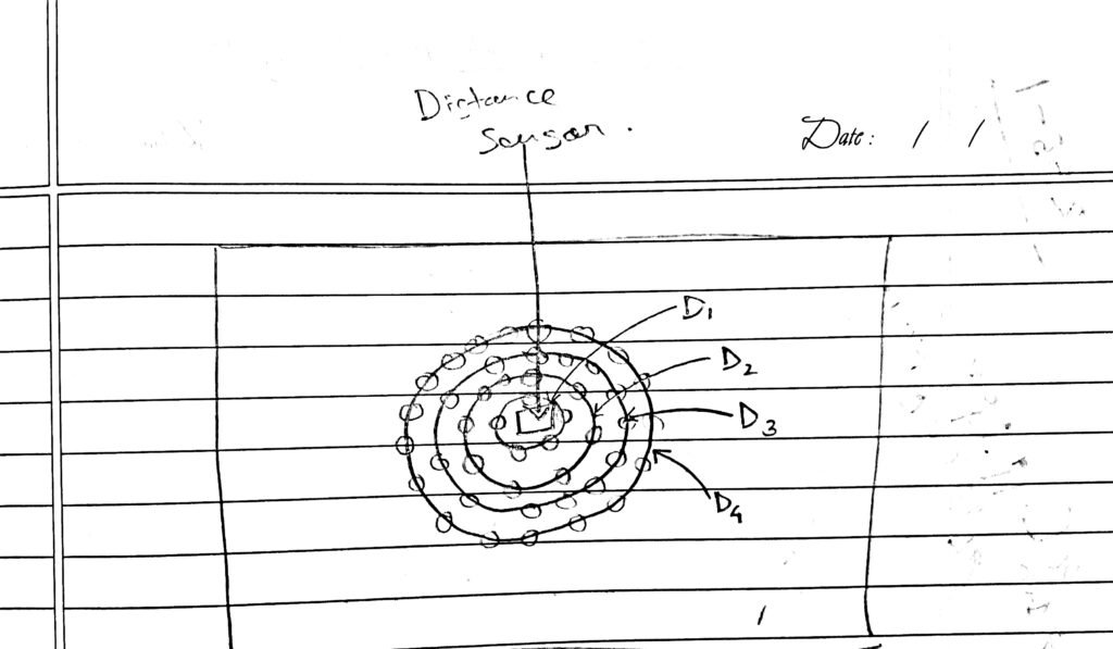
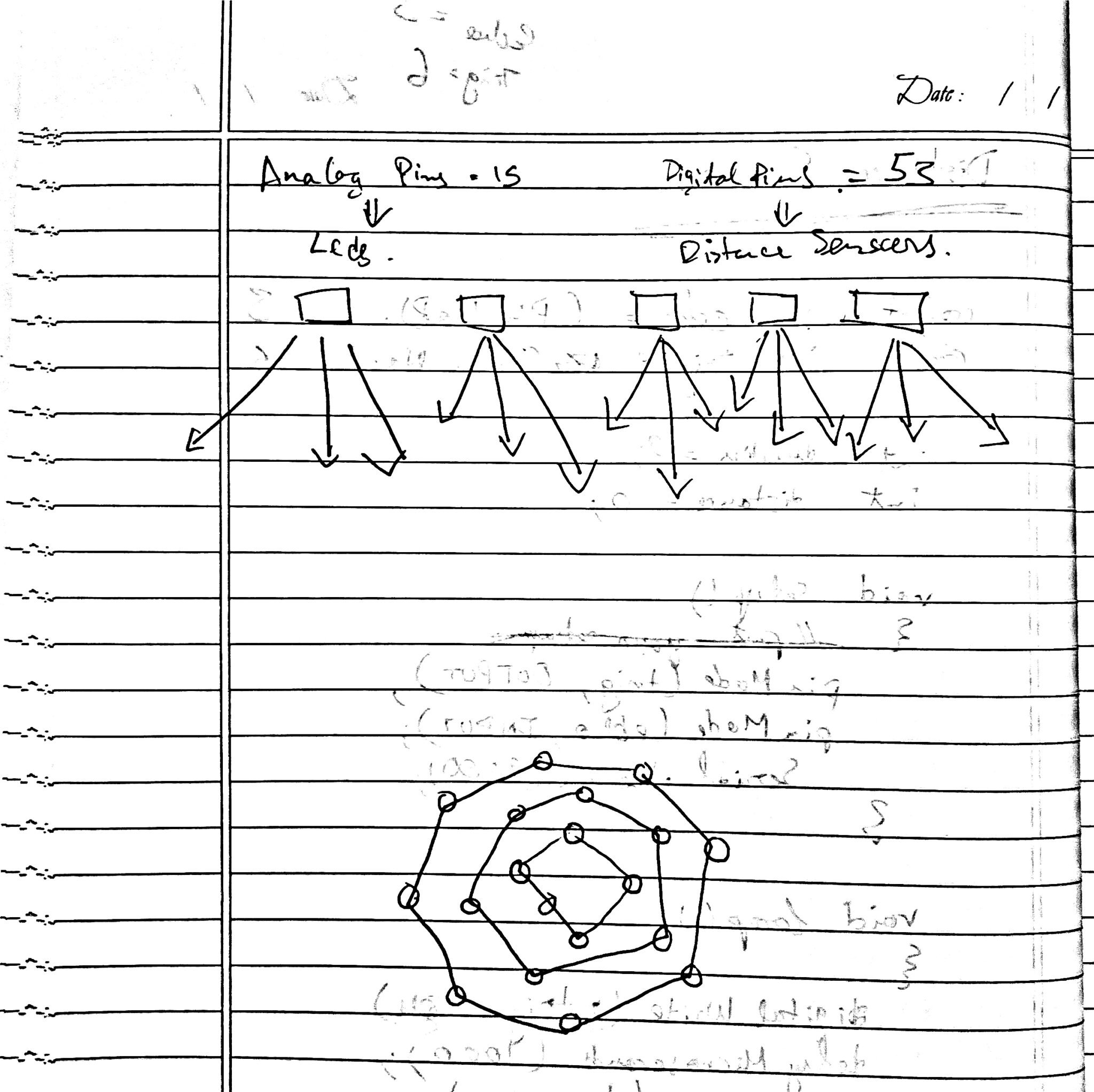
Replacing force sensors, I chose distance sensors to enable ripple activation through mere hand gestures. Additionally, I transitioned from basic LEDs to incorporate the Adafruit NeoPixel Library for Arduino, enriching the project's visual impact. Below is the initial diagram that outlines the project's ideation.
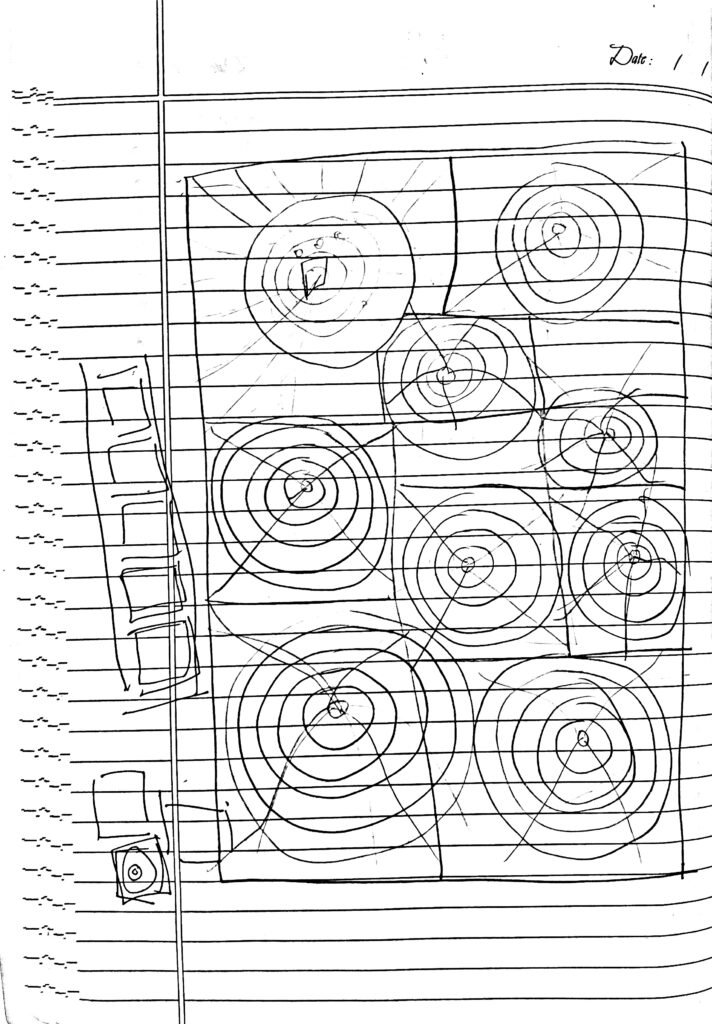
At times, I feared I had taken on more than I could manage with this project, which remains a work in progress. The journey has been filled with trials and errors, offering a wealth of learning experiences. One significant realization was the complexity of integrating five distance sensors with their corresponding light strips into a single, well-insulated circuit—far more challenging than initially anticipated. Yet, here I share the strides I've made so far.
I envisioned the interactive surface to be vertical, imagining a world where humans could create ripples on a vertical water surface, challenging gravity itself. To achieve this, I chose a wooden frame large enough to accommodate my five distance sensors, mounted on a wireframe sheet. This material was selected for its flexibility, allowing easy shaping and manipulation to fit the project's needs.
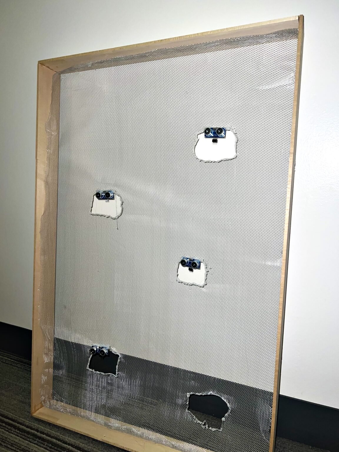
Securing the distance sensors onto the wireframe proved challenging, as I navigated the dual concerns of ensuring a snug fit without risking a short circuit. My initial approach involved stitching the sensors onto the wireframe, a method that quickly proved to be both time-intensive and fraught with difficulties—frequent thread breakage exacerbated by the wire's sharp edges and my own novice stitching abilities.
Turning to the internet for alternative insulation methods that wouldn't compromise the wireframe's aesthetics, I discovered the versatile solution of using a glue gun. This revelation transformed my approach, allowing me to securely affix the distance sensors in place with glue, simplifying the process significantly.

After conducting tests with multiple distance sensors connected simultaneously on the breadboard, I identified the optimal spacing between each sensor. This arrangement ensured that the ultrasonic emissions from one sensor did not interfere with the signals of its neighbors.

Next I fitted all the distance sensors on the wire frame like this picture.
Next, the challenge was to integrate my Adafruit NeoPixel lights with the distance sensors and determine their final appearance. This phase marked a significant departure from my initial design, propelling me into the intricate task of crafting the ripple effects—a journey that, as of now, remains incomplete. Below are several attempts and setbacks, prompting critical questions: How many LED strip circuits would be necessary? I needed to find a balance that wouldn't overwhelm the system, especially when multiplied by five distance sensors. Could my Arduino Mega support this network, or would an external power source become essential? Yet, the idea of further complicating the circuit was unappealing. Instead, I sought to calculate an optimal load that the Arduino could manage efficiently.
This led to the question of how to effectively manipulate my NeoPixels, given their requirement for digital input connections, yet my aim was to program nuanced curves into the lighting patterns. The solution came from my professor, who suggested using loops or leveraging the in-built NeoPixel library in Arduino for this purpose. These approaches opened up new avenues for creatively shaping my light display.
Currently, my focus remains on figuring out the connection between my distance sensors and the light circuit—an ongoing endeavor. I'm committed to pursuing, learning, and seeing this project through to completion.
Here is a small demonstration of how I wanted the outward design to look like.
